This post is technical details about how the enlarging machine is constructed. It may not make much sense if you haven’t checked out part one where we introduced the sculpture enlarging machine.
There aren’t a lot of designs for these things floating around the Internet but I did find some photos and there were a couple of YouTube’s by people who either have one or made one, so I was able to work out a design of my own.
I’m not going to bother to draw blueprints for this because the design is a function of my particular tool set and the specific materials that happened to be lying around the workshop. You probably wouldn’t do it exactly like this from scratch. I’ll just show you what I did and you can make your own set of sub-optimal design decisions adapted to your own scrap metal pile.
Having made this one, I now understand the problem better and I’m almost tempted to scrap it and do a second one right. (I wonder if there is a 12-step program for this kind of impulse?)
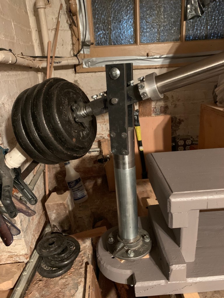
The pivoting post holding the main arm. the satin finshed part is the post, the shiny section above it rotates. 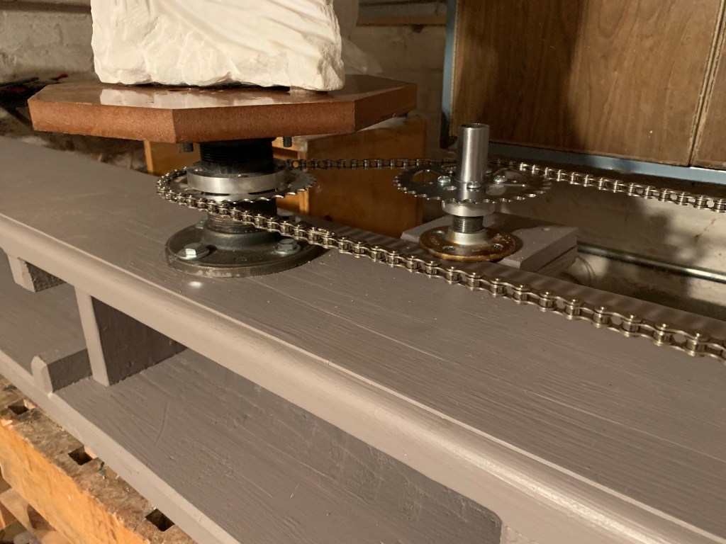
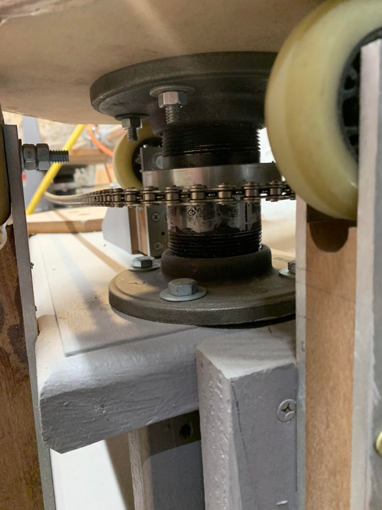
The inner rotating table and the free sprocket to take up chain slack. 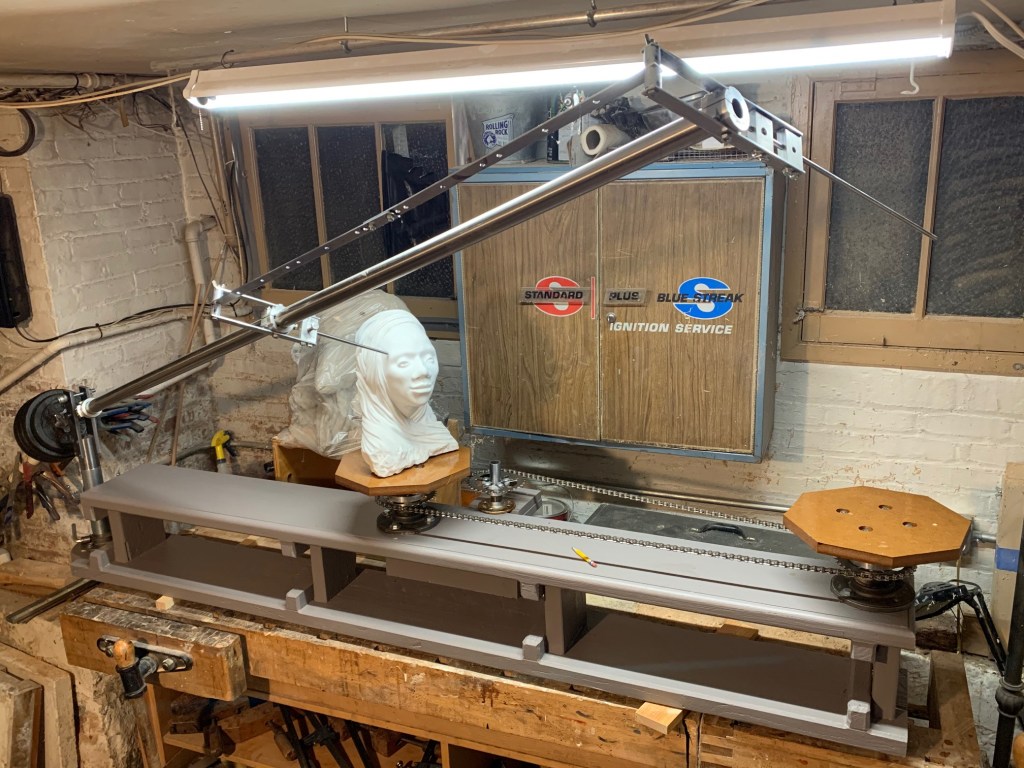
The pantograph mounted to the arm. 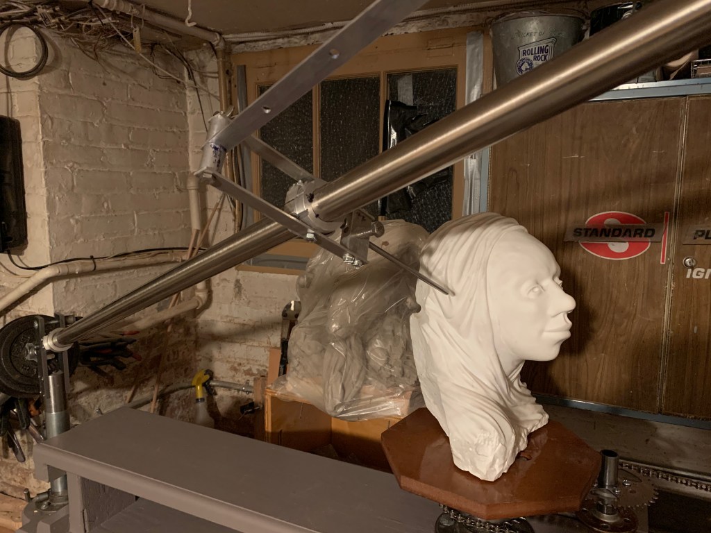
Closeup of the pantograph pivot. 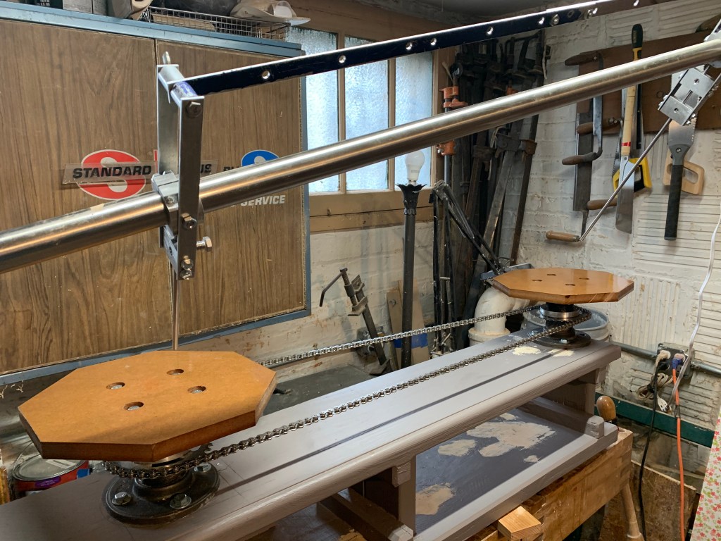
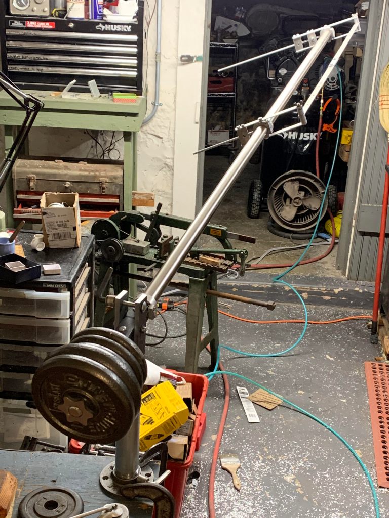
The entire arm assembly bolted to a workbench in the machine area. 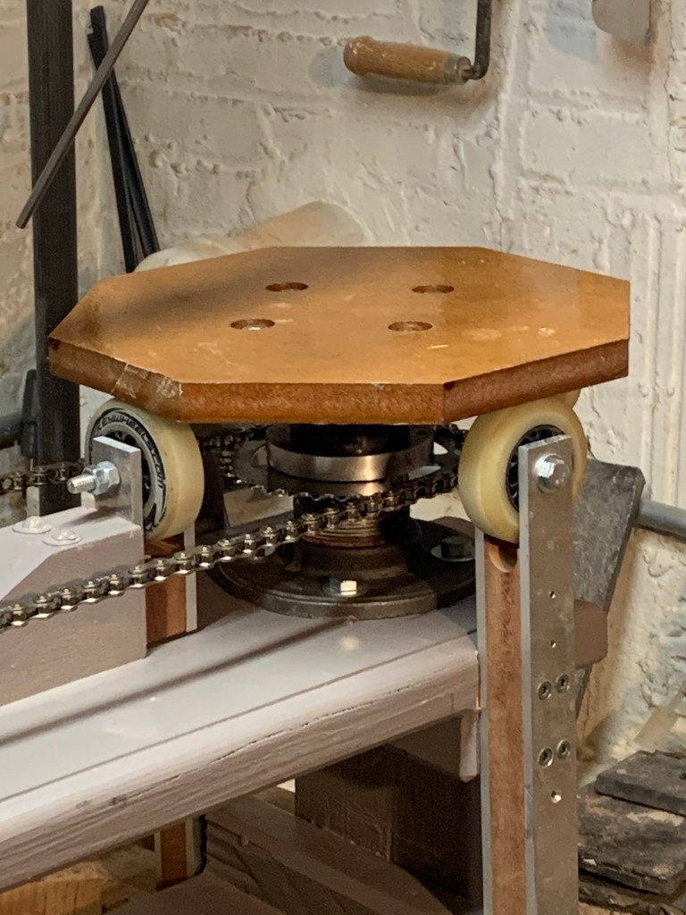
Closeup of the rotating target table and supports. 
Another view of the main arm mounted on a work bench.
The Aluminum Parts
I have a small hobby lathe and milling machine that allowed me to make a lot of parts that wouldn’t have been practical otherwise. Almost everything that swivels or rotates, other than the skate wheel supporting the tables), was either made on the lathe or started as some standard fitting that was tuned up on the lathe or mill. If you don’t have a lathe, you’ll have to do a lot of this differently, but you should be able to hack it somehow.
The round aluminum parts were made on the lathe from blanks I cast from salvaged scrap metal. Casting aluminum is easy. It melts at a much lower temperature than bronze or iron and for simple castings that you intend machine, you can use “green sand” molds that are very easy to make. (We’ll do a posting on this someday!) In this case, I didn’t even need green-sand molds. The aluminum parts were simple and small enough that I was able to machine most of them from raw round bar that I made by pouring the melted aluminum into short lengths of 2.5″ and 3″ iron pipe. I just screwed a cap on the end of six-inch nipples, stood them up in a box of sand, and poured in the metal. When aluminum cools it shrinks by about 2%, which is enough that you can simply shake them out of the pipe. For some of the parts I didn’t even need to cast bar stock. When I salvage aluminum, I usually pour it into muffin tins to make uniform ingots and some of the parts were small enough to machine directly from the ingots.
Eighth Grade Geometry
Having been at least a B geometry student in the eighth grade I was a little embarrassed at how not-obvious some of the details were to me. There are a lot of components that have to be arranged correctly with respect to the various rotational axes to make it work. The key things (as I now fully understand) is that the three main axes of rotation all pass through a single point at the center of the shoulder and the two pivoting axes of the pantograph must pass through the long axis of the arm. This is necessary to ensure that wherever the arm points, the two tips of the pantograph and the center point of the shoulder will fall on a single straight line. If you are trying to understand exactly how it works, that last point is the #1 insight.
Another thing that wasn’t obvious (to me) was that in order for it to work, the center of the main pivot and the tips of the two pantograph pointers must also be in a straight line, which means that the far pointer has to stick out X times farther than the inner pointer. There is an explanation below of how far the near pointer should stick out.
The Platform
The platform supports the two turn-tables and the main pivot post. It’s just dimensional lumber from the big box store painted gray. If I were doing this again, I’d do it differently. It would be useful to have two rails (they could be wood) that a small platform for the inner table could be positioned on and then clamped at 1/X the distance from the main pivot to the far pantograph pointer pivot. (The far turntable never needs to move.)
For this version, I reasoned that I’d probably only want a very few multiples of enlargement and I could just drill holes to bolt the turntable to. But even on my maiden enlargement effort, I’d already have found it convenient to be able to move the inner table to change the enlargement scale slightly. My advice is use rails.
The Post, Shoulder and Boom
The center of it all is the universal joint where the main beam pivots, allowing to swing through 360 degrees horizontally and about 50 degrees vertically (the counterweights bump into the post if you try to go higher and the beam hits the table if you try to go below horizontal. In practice you’ll never want to go higher than 40 degrees anyway.
The vertical post was made from 2.5″ black iron plumbing pipe screwed into an iron floor-flange. I turned the pipe perfectly round on the lathe then bored what would be the top end to make a perfectly smooth internal cylinder about three inches deep. The top is squared off on the lathe as well.
I squared up a six inch piece of solid bar stock and turned three inches of one end of it down to exactly fit in the three inch internal cylinder. It has a shoulder that rests on the squared up end of the vertical post. There is no special bearing–it’s just smooth steel on smooth steel, but it only gets light wear so I think it will be fine for quite a while. If it ever does wear, I can figure out a better bearing. It rotates with a nice silky feel.
The other end of the solid bar has two opposite sides flattened. Two pieces of 1/4″ by 2″ mild-steel flat-bar are screwed into this to form a yoke that can support the horizontal pivot for the main beam. The depth to which I flattened the solid bar was chosen to leave exactly 1.25″ of steel between the flats because I had a piece of 1.25″ square bar that could serve as the balance point for the beam and counter weights. You can see it in the first picture.
I cut up a fancy barbell bar that had a nice screw-on clamp to hold the counter-weights. It fits into a two-inch deep hole drilled long-ways into the 1.25″ square bar and is secured by machine screws. Into the other end of the 1.25″ square bar I bored a 0.75″ hole. Into this I pressed a 2′ length of 3/4″ round bar that the chromed main beam rotates on. The 1.25″ square bar has a 1/2″ hole in the side for the horizontal pin that goes thought it and the yoke. When it’s all set up, the weights almost exactly balance the beam plus the pantograph.
The long arm rotates around a two-foot long, 3/4″ shaft that is press-fitted into the other end of the six-inch bar and secured with a machine screw. Fat aluminum bushings inside the arm (which is 1.5″ thin-walled chrome-plated steel tubing for closet poles) let the arm rotate on the shaft. The arm is smooth and shiny outside but there’s a slight weld bead inside so the bushings had to be pressed into the tube, but once they’re in there they don’t move. The bushings turn very easily on the 3/4″ shaft allowing the arm to rotate freely on its long axis.
The beam teeter-totters on a half-inch steel pin that goes through the yoke, but about four inches above the pivot point there is a 3/8″ carriage bolt that that allows the tension on the yoke to be adjusted. If you tighten the bolt, the yoke grips the 1.25″ bar tightly and holds it steady.
There is some hidden complexity in the post and yoke that doesn’t come through. There are two levers that lock the rotation of the post and the tilt of the arm. Once you’ve located a point on the model you’d lock the arm in position while you work on the target. I think you can see the levers if you look at the post.
The Pantograph
The pantograph is all aluminum. It is just a parallelogram mounted on the arm in such a way that the center line of the swinging arms intersect the the center axis of the arm (check the pictures). The pointers are always parallel to each other and point back at the main axis of the arm no matter where you swing it or how it rotates on the long axis.
The fittings that fasten around the arm were turned on the lathe from aluminum. They have a slice through one side that allows them to be clamped tightly by turning a pair of screws. The rest of the pantograph is cut from odds and ends of bar stock.
The inner pantograph pivot has to be set for whatever enlargement scale you’re using, so the linkage between them has holes drilled for common enlargement scales. This was a design mistake. It should have a more precise screw mechanism. The first time I tried the machine I had the pantograph ever so slightly off, making the pivot arms not quite parallel, which resulted in a systematic distortion of the location of the target tip. If the arms aren’t perfectly parallel the target tip’s location will be significantly different depending on the angle of arms. The linkage differed from the distance between the pivots by only a little more than 1/16, but it translated to more like an inch of variation out at the tip of the target pointer!
Rotating Tables
The rotating table mounts are made from short lengths of 2″ black iron pipe mounted in plumbing floor flanges, one pipe-flange pair on top, fastened to the table and another pipe-flange pair on the bottom, fastened to the platform. See the pictures below.
The pipes were bored smooth inside and a piece of solid aluminum bar was pressed into each and squared off at the top. Then each was bored to accept a piece of 1″ shaft that the two halves rotate around. In the picture on the right the two halves are pulled apart to show how the aluminum core and the 1″ shaft inside. They movement is very smooth and solid.
They’re OK so far, but if I were going to do this again, I’d avoid the steel-on-aluminum bearing by pressing steel pipe into the aluminum and then boring the steel to the size of the shaft. That would make a longer lasting bearing surface.
The only wrinkle is an additional fitting to hold the chain sprocket. The sprocket is fastened to the aluminum core of the top half. The polished stainless steel underside of the sprocket is one bearing surface and the aluminum and steel of the bottom half is the other making a very slick contact surface. This would not be a very durable bearing if the two faces were constantly being rotated against each other but it seems completely adequate in this setting. It seems fine, but if it ever does look like wear could be a problem, I think a thin teflon disk inserted between the surfaces is all it would take to remedy it.
The chain is tensioned by a third sprocket that freewheels on another pivot mounted on an adjustable plate. It can be seen in some of the pictures above.
The turntable as it is in use. 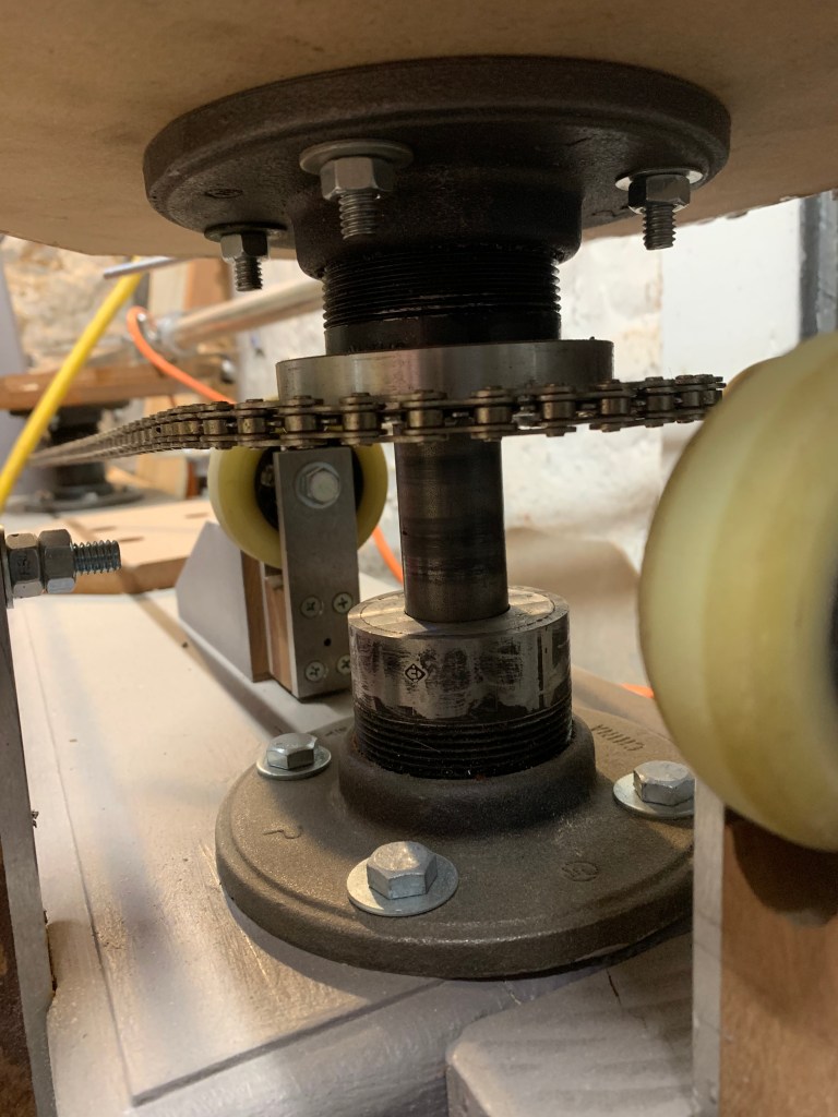
The top piece lifted up to show the aluminum core and the steel shaft. The underside of the chain sprocket is polished hard steel that shows no sign of wear and has no visible tendency to wear the lower surfaces.
Four urethane skate wheels are positioned under each table to provide additional stability because the target table could hold considerable weight. The wide diameter of the pivots combined with the skate wheels together make it strong enough to for a person to stand on without any deflection or loss of ability to rotate.
Assessing the Design
It works well but there are several things I’d do differently on enlarging machine 2.0.
- There should be a pair of rails that the inner turn-table clamp to so it can be positioned anywhere. Simply bolting it to the chassis is crude and I can see it will be a problem if I ever have to do a precise enlargement.
- The linkage bar for the pantograph has the same problem–I relied on holes to position it, but something continuously adjustable would be much better.
- The pantograph pointers also need a more flexible adjustment.
- Putting the universal joint on top of a post was an interesting idea, but probably not worth the trouble. The reason was that with the pivot elevated, the tables could be stepped down to put the work at a more convenient level. After having used it, I think it was too much solution for the problem. It might be more worth doing on a big rig.
So all in all, it’s pretty good. Second time around I’d certainly rework the pantograph and the inner table adjustment mechanism, basically for the same reason. They don’t adjust finely very well. Also, the pantograph is a little crude all around. Next time I should bite the bullet and do a proper CAD drawing in Autodesk. It would be an interesting exercise to then print foundry forms and cast the parts for it, rather than simply machining them out of aluminum cupcakes.
Where To Go From Here?
The next step is to enlarge something. I’ve done a couple of pieces I wasn’t happy with that went back into the clay bucket. Maybe for the piece I’ll post about each step along the way.
