I’m a sculptor, but I’m also interested in the history of sculpture so I tend to experiment with tools that I can’t honestly claim to have any need for. Call it frivolous, but it sometimes works out. I built my first pointing machine before making a piece I could use it on and now it’s my go-to technique.
Pointing machines are for copying a 1:1 scale model into stone. A sculpture enlarging machine is the same basic idea, but it lets you copy a model at scales that aren’t 1:1. They are most often used to enlarge but you could as easily use it to make a miniature copy of a big original. Unlike the pointing machine, the enlarging machine isn’t usually used in the carving phase. It’s used to enlarge a plaster model into a full size clay version which can then be cast.
This general design for sculpture enlarging machines has been around since at least the 19th Century, but try finding plans! So while the principles are well known, the design is my own. I do more bas-relief than sculpture in the round, but I thought I had a clever way to make this old design work for flat panels too so it seemed worth a try. Once I got into it, I realized that my idea for handling flat panels would be cumbersome if it worked at all, so for now, I’m keeping it simple and sticking to sculpture in the round. Maybe I’ll revisit the panel idea down the road.
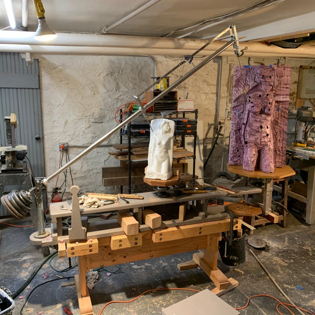
The machine is now engaged in its maiden application. In the first picture below I’m using it to make a styrofoam armature (for an ongoing project that is the subject of a video series.) The armature phase is somewhat crude–the idea is the leave some space for clay. We’ll get more precise later.
The gray-painted part is the chassis of the enlarging machine. It’s temporarily clamped to my low workbench, which is the blonde wood thing it’s sitting on.
When you go through the exercise of designing and building something like this, you can lose any sense of what is obvious, so in case the function is not clear, here’s what it does.
- The goal is to start with miniature model (in this case 1:2 scale) and enlarge it to full size, i.e., 2X. The model shown is plaster cast from a clay original.
- You want to be able to put the near pointer on some key spot on the model and have the far pointer automatically located at the corresponding point in space, except multiplied by 2X in each of the three spatial dimensions.
- In the picture, the point is on the model’s shoulder. I’ll build out the shoulder of the full size copy until it just meets the target pointer. After doing the same for a number of adjacent points you can fill the gaps with clay.
- For practical reasons, I’m doing it in two phases. Phase one is building the armature, in this case out of styrofoam insulation panels (a miracle material, BTW.) In phase two I’ll get more exact with clay.
- If you’re enlarging, the original goes in the middle. If you’re reducing, the original goes at the end and the target goes in the middle.
- The arm swings and rotates and the pantograph swings about 90 degrees (plus minus 45 degrees) allowing you to come at a given point from a wide three-dimensional range of angles.
- The original and the target are sitting on two rotating tables that are connected by a bicycle chain so that they are constrained to rotate together. This lets the machine get to all sides of the model.
Note: I’m going to assume you’re using styrofoam for an armature because for a large pice, the traditional solid clay over a metal armature would require an industrial-strength table. If you’re at a level to build something like that you won’t be bothering with this post!
How much space you leave for clay is a matter of convenience. It can be half an inch, an inch, or even more. My experience so far is that too little space will cause it to dry out rapidly and too much requires a lot of clay and gets heavy. So far, I feel like I’ve erred on the side of too little. I’ve added and removed material relative to the original slightly in some places, and where I’ve removed it, I’ve bumped into the styrofoam. It’s not that hard to chop out, but it’s a nuisance and it interferes with your flow. The more precisely you intend to enlarge, the less clay you need.
Confession: Part way into the armature I discovered that I’d adjusted the machine incorrectly, and it systematically distorted the result. I corrected the problem and cut the styrofoam down in some places and built it up in others before proceeding. The problem was that the armature linkage was slightly short making the pointers out of parallel. Just a little, but it meant that the pointer tip’s location changed depending on the angle of the beam. You’d notice instantly doing precise work, but I got pretty far on the styrofoam without noticing it. The way I diagnosed it was to mark a point on the model and put the model pointer on it coming from the left. I put a block of wood on the target that was exactly the right high to put a with a mark on the top where the target pointer touched. As I swung the beam up and right, keeping the model pointer in the same place, the target pointer didn’t stay in the same spot–it described a circular arc, lifting up above the block then coming back down to the right. This was the clue that the pointers were spreading slightly. I fixed the linkage length and the problem went away.
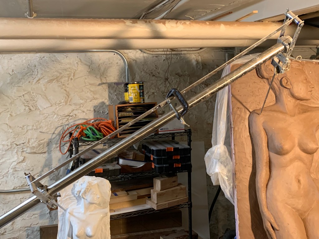
In the picture to the right, I’ve gone at it a little more precisely with the clay. Unsurprisingly, it looked somewhat different full size. A lot of things didn’t look quite right blown up, so what you see is a mix of exact measurement plus a certain amount of freehand in places. Note that the second picture is logically half-way through the third of five steps. After finishing the full-size clay, the next step will be to cast it in plaster and the final step will be to use pointing to transfer it into stone. Of the five steps, the last will be the most laborious but the relative amount of work can differ according to your practice. Some sculptors will bring the small model to a high degree of exactness and require precise enlargement. Others will use the model only to work out approximate relationships and do much more creative work on the full size clay.
More Detail
I oversimplified a little in the description above. The description is accurate as far as it goes but it makes more sense to describe why it works in terms of spheres.
The center of everything is the imaginary swivel point for the main beam. It’s a “universal” joint, which means it can swing up and down and side to side around the same point, at the same time. The vertical post swivels 360 degrees around that vertical axis and it swings up to to a maximum of about 50 degrees vertically on the horizontal axis before the counterweights on the beam will bump into the post. 50 degrees is about as much as you’d ever want for reasons I’ll explain below.
The universal joint means that any given point on the beam sweeps out a section of a sphere that is centered on the point where the horizontal and vertical axes cross. There’s one more axis that intersects this same point. The beam itself turns freely around its own long axis which also crosses that imaginary point.
The sphere-sections we most care about are the two swept out by the inner and outer pivots of the pantograph. The equators of those spheres are on a single plane that includes the tops of the two tables and the point where the axes of the main beam all cross. The small sphere is 1/X the diameter of the big sphere, where X is the scale.
The reason the machine works is that at any combination of beam angles, the pantograph pivot-points create pairs of similar triangles that share the apex at the main pivot point. Similar means the corresponding angles are the same but the corresponding sides can be different (but they have to be in proportion.) The triangles are formed by the angle between the boom and the horizontal table-tops, the angle of the table tops and their axes of rotation (they ae vertical, so they are both 90 degrees) and the angle of the boom and the axes of rotation of the table tops.
A pair of triangles are similar if two of these angles to be the same, and it’s easy to see that two of them are: they share the boom/horizontal angle and the angles of the table-axes to the table-tops are both fixed at 90 degrees. (With two the same the third pair have no choice but to be the same because the three angles of a triangle have to add up to 180 degrees.)
Another thing that’s right out of your geometry text book is that if two triangles are similar, then all of their corresponding sides are in the same proportion. We fixed this at 2x in this example and placed the tables and the pantograph pivots accordingly so we already assured that two of the pairs of sides are in the same proportion. Actually, this fact plus the boom angle would also guarantee similar triangles. Either way, all the other pairs of similar triangles that we can derive from the sides of the main triangles will be in that same proportion because the corresponding side that we are working from will be in that proportion.
That’s the heart and soul of the design, but it wouldn’t do much good without the pantograph attached to the beam because the apex of the triangles that we would want to use for scaling up are are inside the beam. The geometry of the pantograph creates more pairs of similar triangles based on the corresponding sides of our main similar triangles and these triangles define pairs of points that are well away from the beam. Because they are related by similar triangles with an apexes at the centers of the tables, the points they define must be proportional distances from those table centers. Once you see how the main triangles of beam, pantograph pivots, and table center must be similar, you can apply the same logic to triangles formed by the pantograph. It’s easier to see than to follow in a description.
We’ve been ignoring the beam’s axis of rotation to keep things simple, but it actually doesn’t change anything. As long as you imagine the beam rotated to some fixed angle, the same system of pairs of similar triangles can be constructed, proving that it doesn’t change the basic geometry to rotate on that axis.
A Geometric Limitation
We said that the main purpose of the pantograph arms was to locate the point that we want to use for scaling up outside of the beam. That’s oversimplifying somewhat. Imagine that we omitted the pantograph and just screwed the feelers directly into the beam.
If we did that, the model feeler could only reach points that are exactly on the intersection of the imaginary sphere and the model. If you imagine a super-simple cylindrical model, the intersection would be a parabola-shaped slice through the cylinder. Where the cylinder meets the table, i.e., with the beam horizontal, the pointer would hit it at almost a right angle, and at the highest useful angle of the beam the pointer would be tangent to the cylinder, i.e., just scraping past it at 0 degrees. You could rotate the tables to get the pointer tip to points around the cylinder at any height lower than the height at which the pointer was tangent but you couldn’t reach any points on the cylinder that are above that maximum height where the sphere intersects the model. (Of course, if you had a more complex shaper there’d be lots of places you couldn’t reach even if they were below the highest point you could reach.)
Geometrically, the problem is that the higher you swing the boom, the farther the sphere is at that level from the vertical axis of the table. If you lift the boom high enough, it will be further from the center than the outside of the model is. So the second main function of the pantograph is to give you some flexibility to reach points that aren’t exactly on the intersection of the sphere and your model.
The third function of the pantograph, the one you’re most aware of when using it, is that it lets you come at any given point from a wide range of angles. Most models are very far from being cylinders, so this is something you use constantly.
The Beauty Of Synchronized Tables
You can easily imagine doing this without rotating synchronized tables. For instance, the model and the target could be manually rotated a fixed amount and clamped down. But having the tables chained together lets you move and adjust the angle at will. You’ll use this all the time.
Everything works better with the pointers near the middle for many reasons. Surface features are less often in the shadow of other features when accessed from the front. Another reason is that at extremely low angles, small errors get magnified.
Yet another reason is that for most points the extra degree of freedom from the rotating tables gives you a much wider range of angles of attack.
Summing Up
So far I’m loving this thing. It’s been a learning exercise, both in the making and in the using, but I think I’ve got the hang of it. It’s one of those things where adjusting the amount of work something is really changes the process. Being able to experiment at 1/2 or 1/4 size is a game-changer for me. It’s agony to have to make a major change to something full size. I love being able to experiment in miniature.

Very nice Peter!
LikeLike